Full Adder Circuit Diagram 7483 Circuit Diagram For 4 Bit Bi
Circuit diagram for 4 bit binary adder using ic 7483 » diagram board Design and implement 9's complement circuit using ic-7483 74hc83 full adder ic pinout, datasheet, equivalent working, 57% off
Circuit Diagram For 4 Bit Binary Adder Using Ic 7483 - IOT Wiring Diagram
Full adder 7483 full adder pdf Circuit diagram for 4 bit binary adder using ic 7483
Circuit diagram for 4 bit binary adder using ic 7483
7483 circuit diagram full adderCircuit diagram for 4 bit binary adder using ic 7483 7483 full adder circuit diagram circuit diagramCircuit diagram for 4 bit binary adder using ic 7483.
4-bit adder-subtractor in digital circuitCircuit diagram for 4 bit binary adder using ic 7483 » wiring flow line 7483 circuit diagram full adder7483 adder binary nap requires parallel.

Circuit diagram for 4 bit binary adder using ic 7483
15 full adder pin diagram7483 4-bit binary full adder ic 74ls83, 41% off Circuit diagram for 4 bit binary adder using ic 7483Circuit diagram for 4 bit binary adder using ic 7483.
7483 full adder circuit diagramCircuit diagram for 4 bit binary adder using ic 7483 Circuit diagram of full adder 7483 logicCircuit diagram for 4 bit binary adder using ic 7483 » wiring core.

Four bit adder or subtractor using 7483
Design and implementation of a bcd adder circuit using ic-7483Circuit diagram for 4 bit binary adder using ic 7483 » wiring core 7483 ic 4-bit binary full adder with fast carryCircuit diagram full adder subtractor.
8 bit full adder circuit diagramCircuit diagram for 4 bit binary adder using ic 7483 Circuit diagram for 4 bit binary adder using ic 7483Circuit diagram for 4 bit binary adder using ic 7483 » wiring core.
Four bit adder or subtractor using 7483
.
.


Circuit Diagram For 4 Bit Binary Adder Using Ic 7483 - IOT Wiring Diagram

Four Bit Adder or Subtractor using 7483 - EEES.IN

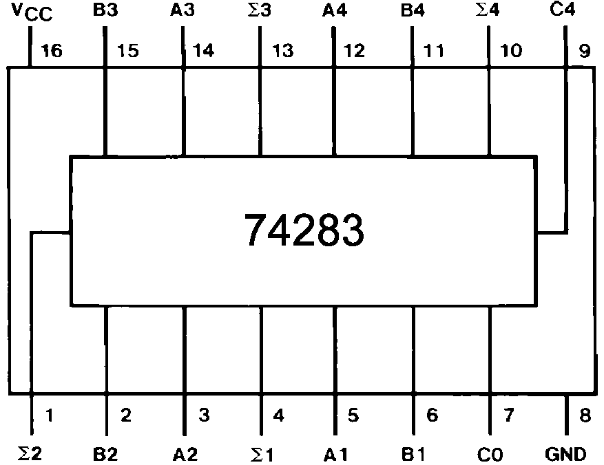
7483 4-bit Binary Full Adder IC 74LS83, 41% OFF

Four Bit Adder or Subtractor using 7483 - EEES.IN

Circuit Diagram For 4 Bit Binary Adder Using Ic 7483 - Wiring Flow Line

Circuit Diagram For 4 Bit Binary Adder Using Ic 7483 - Wiring Flow Line
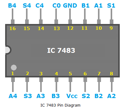
15 Full Adder Pin Diagram | Robhosking Diagram

Circuit Diagram For 4 Bit Binary Adder Using Ic 7483 » Wiring Flow Line